

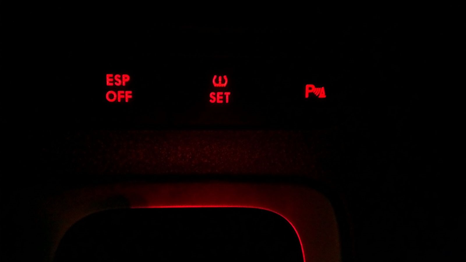
I completed the retrofit of TPMS I had already activated by coding (see this link) by installing the SET button connected to the ABS control unit.
DIY about it there are lots of on the internet so I just try to add some info.
In this guide, the only difference from the Golf MK6 sedan is the part number of SET button.
Material
SET TPMS button cod. 5M0927121 A REH (specific for Golf Plus)
Plug&Play Harness by Kufatec (cod.35558)
Equipment
Torx 20
Tools for plastic dismantling
VW tape
Fairlead
Scissors
Electrician Ties
Installation
Installation is fairly simple.
Through Plug&Play harness Kufatec are taken from the button ESP/ASR the +12V signal to the SET of the TPMS, the +12V and GND for key lighting.
The cable with the SET signal TPMS is brought to the ABS control unit connector (pin #35).
Step1 — Dismantling the center console
If he has the DSG set the lever in D or S and Instrument Cluster off.
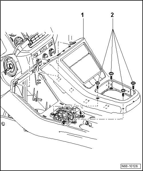
To remove the central console must force slightly the frame of the gear lever to completely lift (it is inserted under pressure). It starts from the lower right. Beware of teeth that are plastic and break easily.
Removed the frame just unscrew the 2 or 4 Torx screws that you see -2- (in my case I have the housing for 4 but only 2 were mounted …).
At this point, starting from the point of the screws lifting the console that is simply stuck and it raises the whole -1- block.
In doing so they are accessible to the space for the TPMS key and the ESP/ASR button.
Step 2 — Installation and wiring SET TPMS button
From the center console remove the cap and insert the TPMS button.
Remove connector from the shell white of ESP/ASR button.
Cut the cable tie holding the black 6-pin connector and remove the white shell.
To remove the black connector, pull the clip on the side of white shell and remove it.
Take Kufatec wiring and the small 3-pin connector Male in package.
The connection diagram is as follows:
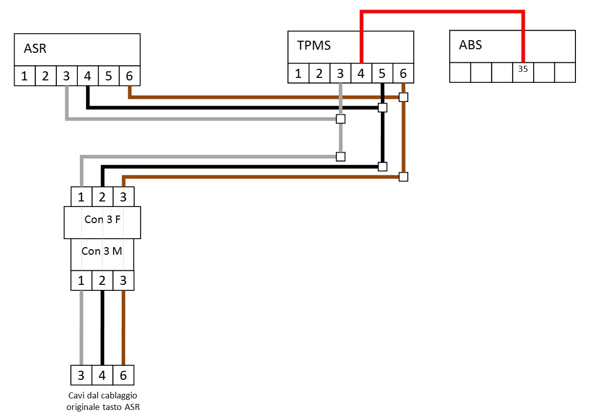
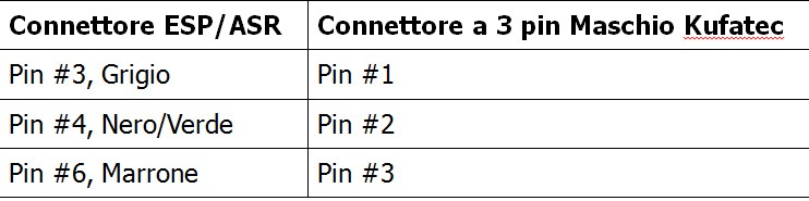
Using a thin knife to open the ESP/ASR connector and remove the following pins to insert them into the 3-pin connector Male Kufatec in this order:
To remove the pins from the ESP/ASR press connector with the blade of a small screwdriver on the tab that appears above the pin while lifting it from its seat.
Close the 3-pin connector Male so wired and plug connector 3-pin female is part of Kufatec wiring.
At this point the three free wires on Kufatec wiring will have to be inserted in place of the pin previously extracted from the ESP/ASR connector according to the order shown in the table.
The wiring that I had bought all gray wires but is stamped on each one the equivalent color code that I report.
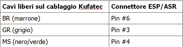
Close the black connector ESP/ASR and reinsert it into the white box. Put a clamp to lock it.
Finally, place the orange connector Kufatec cabling in the new TPMS button.
Step 3 — connection to the ABS control unit
The cable remains free is what is connected to the ABS control unit.
I passed behind the metal support of the ashtray and … twist I switched from right in the pollen filter area.
Removing the filter, at the top right there is a cable passage to the motor that comes out just behind the ABS control unit.
This avoids detours and the need to remove the battery. This "tricksy" I taught it to my mechanic friend: I would have never arrived!
Unfortunately I have no photos :(.
The cable simply goes through the cable tunnel.
To remove the ABS connector must completely lift the vertical block.
The connector is released.
At this point it is necessary to remove the top cover which is held by 4 tabs simply to be bent with the blade of a screwdriver.
Then it removes the black strap that holds the harness: careful to note down the position as the new band will be called in the same way.
To find the Pin #35 on the connector refer to the chart below:
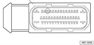
Having identified the position is to be removed the rubber plug which seals the housing.
Before inserting the pin is released Kufatec wiring the connector block (purple tab).
To help them slide it just better to spray it with a little of WD-40.
To replace the connector you follow all the steps backwards.
The added cable is clamped on the wiring harness of the ABS and the remaining cable is fixed behind the cabling of the SET Button.
Step4 — fitting center console
The console is remounted in exactly the opposite direction to disassembly.
Step5 — Verification
Once reassembled everything occurs if everything is OK, that is:
1. Turning on the lights the SET button should light
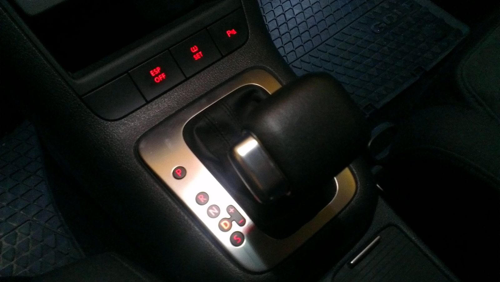
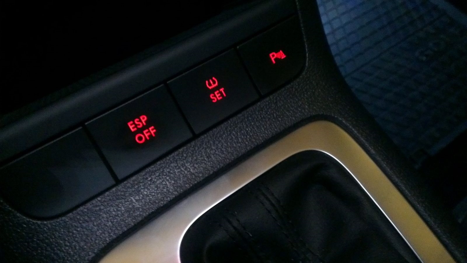
2. When you switch on the ignition and press the SET button for a few seconds should turn on the yellow light in the speedometer followed by an audible alert.
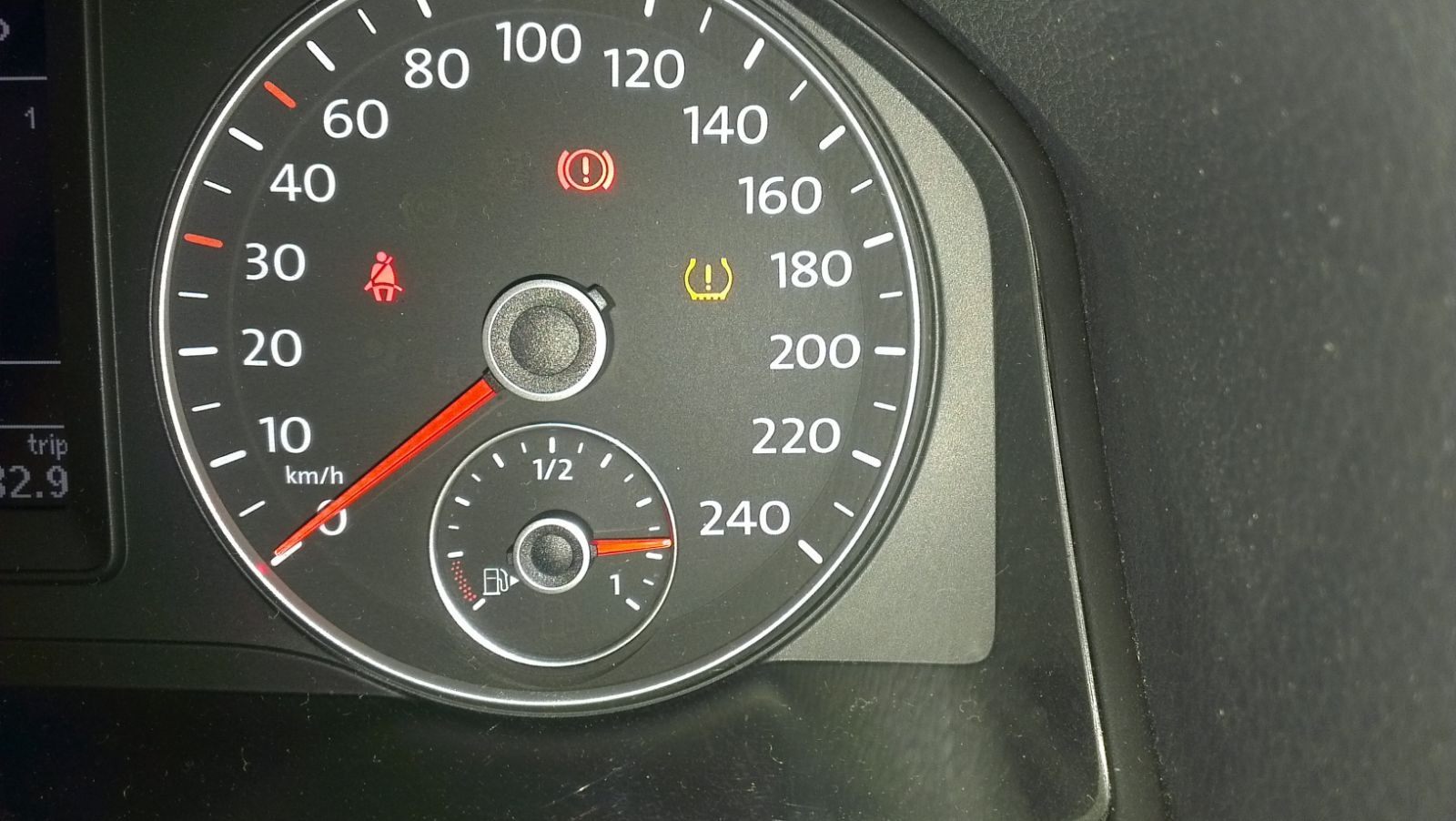
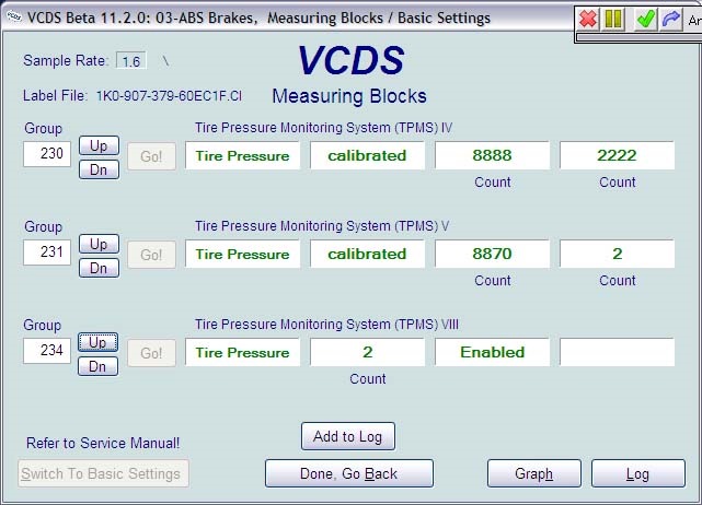
3. With the VCDS accessing ECU3 (ABS) -> Measuring Block-> Group 231-> Go in the 4th box should appear 0 to confirm that the system is in the process of learning.
Learning ends when in the 4th box appears 2. The duration of this phase is variable and depends on the road conditions you ride. Sometimes it also puts 500 Km.
Enjoy!


Комменты 1
Haha! Great! Thanks for sharing
Пожалуйста, войдите, чтобы пользоваться всеми функциями Drive2
Войти